Motor Coupling for Packaging Machine Rollers
Introduction
In the world of packaging machinery, motor coupling plays a crucial role in ensuring the smooth and efficient operation of the rollers. This article will delve into the various aspects of motor coupling for packaging machine rollers, providing in-depth insights into its importance, selection criteria, and mechanical coupling mechanisms.
Why Motor Coupling Matters
Motor coupling is a vital component that connects the motor shaft to the roller shaft in a packaging machine. It facilitates the transfer of power and torque, enabling the rollers to rotate and perform their designated tasks. Without a reliable motor coupling, the rollers’ performance and overall machine efficiency may be compromised.
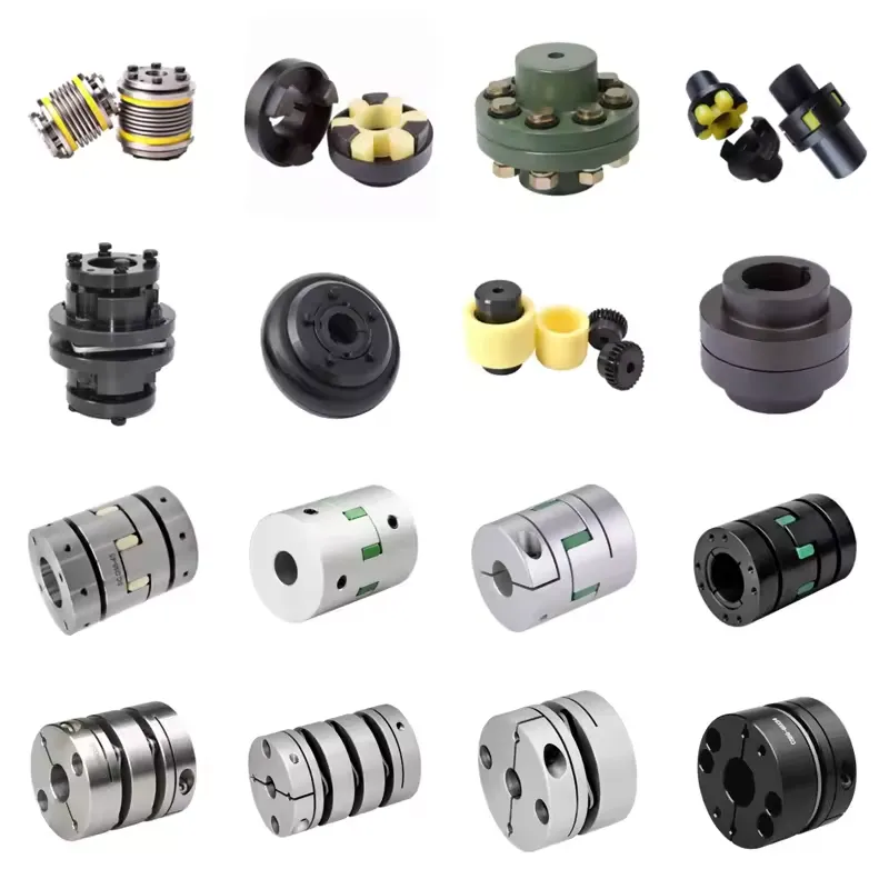
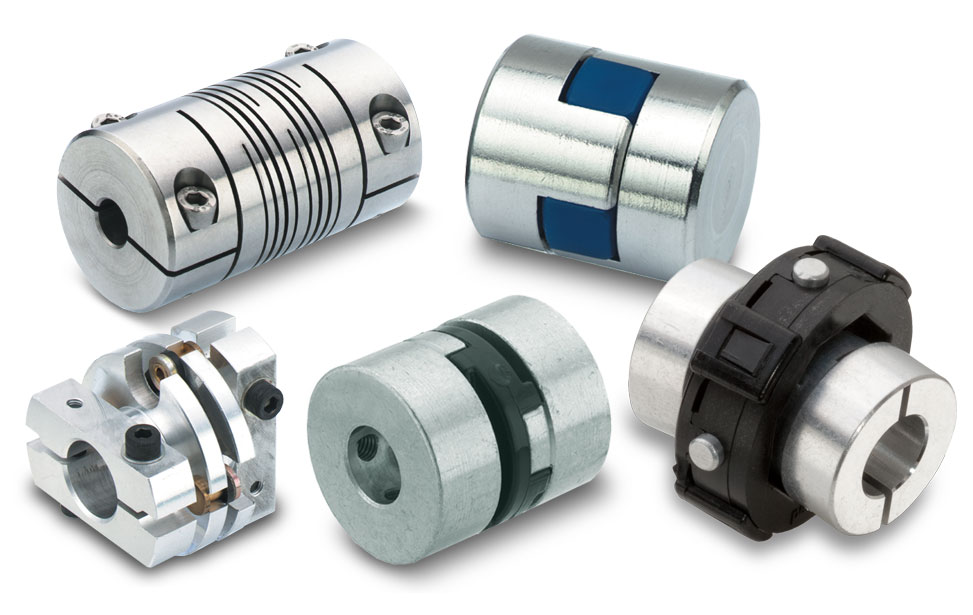
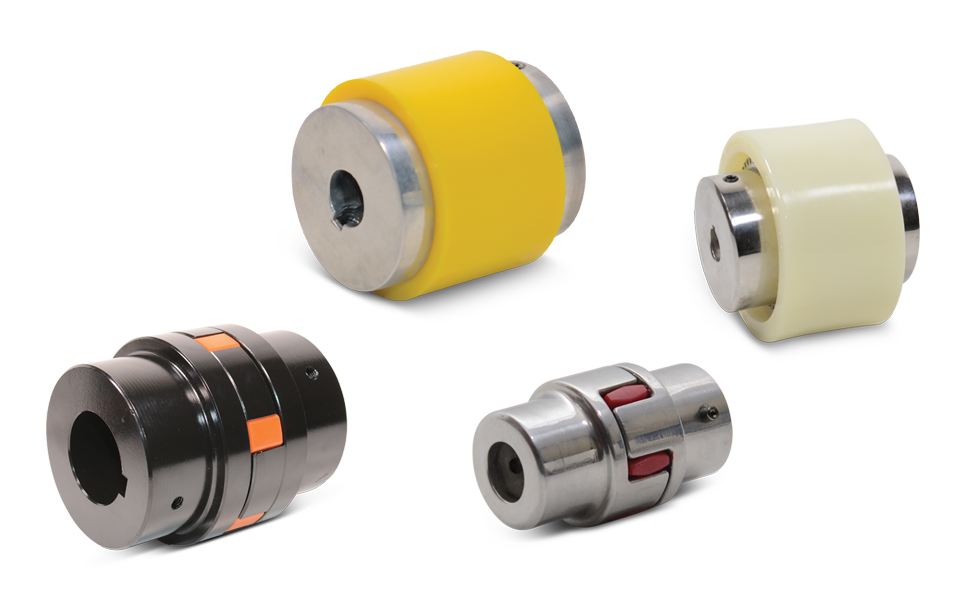
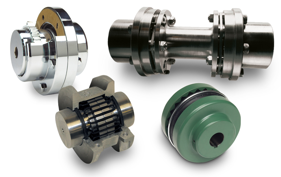
Types of Motor Couplings
1. Elastic Couplings:
– Elastic couplings, such as rubber couplings, provide flexibility and damping capacity, reducing vibration and shock transmission between the motor and rollers.
– These couplings are highly efficient in compensating for misalignment between shafts.
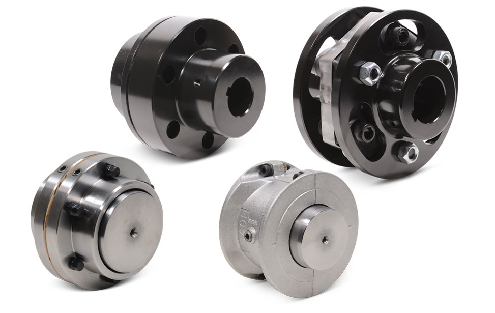
2. Gear Couplings:
– Gear couplings offer high torque transmission capabilities, making them suitable for heavy-duty applications.
– They provide excellent torsional rigidity, ensuring precise and synchronized movement of the rollers.
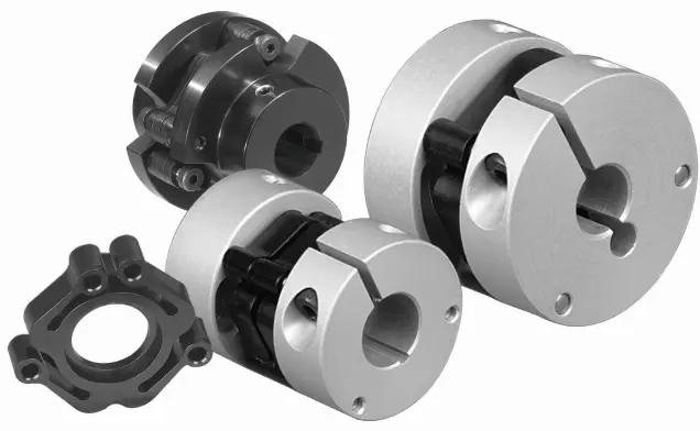
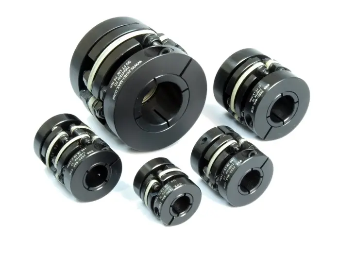
3. Disc Couplings:
– Disc couplings are known for their compact design and high torque capacity.
– They are resistant to misalignment and can handle axial, angular, and parallel displacements effectively.
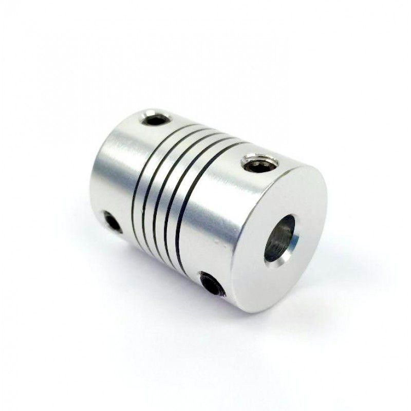
4. Grid Couplings:
– Grid couplings excel in high-speed applications, offering high torque density and backlash-free operation.
– They are designed to provide excellent shock absorption and vibration dampening, minimizing wear and tear on the rollers.
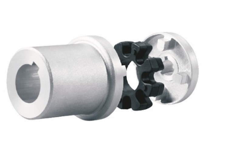
5. Oldham Couplings:
– Oldham couplings are ideal for applications with significant misalignment.
– They consist of three components: two hubs and a center disk, allowing for axial and angular compensation.
Choosing the Right Motor Coupling

To select the appropriate motor coupling for packaging machine rollers, several crucial parameters and practical considerations need to be taken into account:
1. Torque Capacity:
– Consider the required torque rating of the motor coupling to ensure it can handle the load demand.
2. Misalignment Tolerance:
– Evaluate the degree of misalignment that may occur during machine operation and choose a coupling that can compensate for it effectively.
3. Speed and RPM:
– Determine the speed and rotational requirements of the rollers to select a coupling with the appropriate speed rating.
4. Environment and Temperature:
– Assess the operating environment’s conditions, including temperature, humidity, and presence of chemicals, to choose a coupling with suitable material properties.
5. Maintenance and Installation:
– Consider ease of installation, accessibility for maintenance, and the overall reliability of the coupling design.
Mechanical Coupling of a Motor
The mechanical coupling of a motor refers to the connection between the motor and the driven mechanism. It ensures the transfer of power and torque while accommodating any misalignment or vibration. Motor couplings are designed to provide a reliable and efficient link between the motor and the rollers, enabling smooth and precise operation.
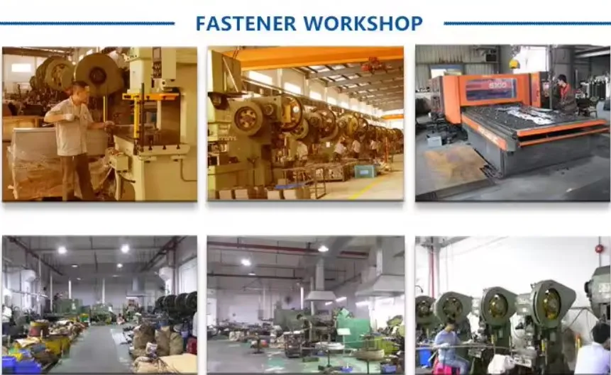
About HZPT
HZPT is a modern enterprise located in Hangzhou, Zhejiang Province. We specialize in the research, production, and international trade of motor couplings and other power transmission products. With a focus on innovation and a commitment to integrity, we have established ourselves as a renowned company in the industry.
Here are some key reasons to choose our motor couplings:
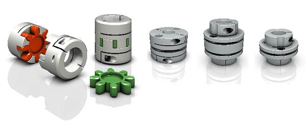
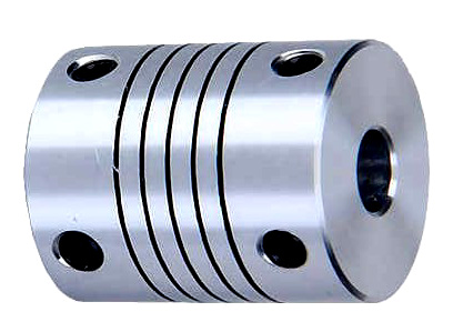
1. Wide Range of Products:
– We offer a comprehensive range of motor couplings, including drum couplings, spring pin couplings, serpent spring couplings, universal couplings, star couplings, expansion couplings, membrane couplings, and tire couplings.
2. Quality Assurance:
– We have a rigorous quality management system in place, supported by our own research and testing departments. Our certifications, including CQC, ISO, and CE, attest to our commitment to delivering high-quality products.
3. Technical Expertise:
– Our team of experts possesses extensive knowledge and experience in the field of motor couplings. We provide excellent sales support and technical assistance to our customers.
4. Global Reach:
– With a customer base spanning Asia, Europe, Africa, and North America, we are continuously expanding our international presence. We aim to become a globally influential international group.
5. Customer Satisfaction:
– We prioritize customer-centricity and strive to exceed our customers’ expectations. Our business philosophy revolves around putting people first and providing top-notch service to foster mutually beneficial partnerships.
With our exceptional products and company advantages, we invite you to collaborate with us for all your motor coupling needs.